

Introduction
After buying the Digispark board it can sometimes be a bit of pain in finding out how to properly set it up and get some code on it. Hopefully this will fix all that.
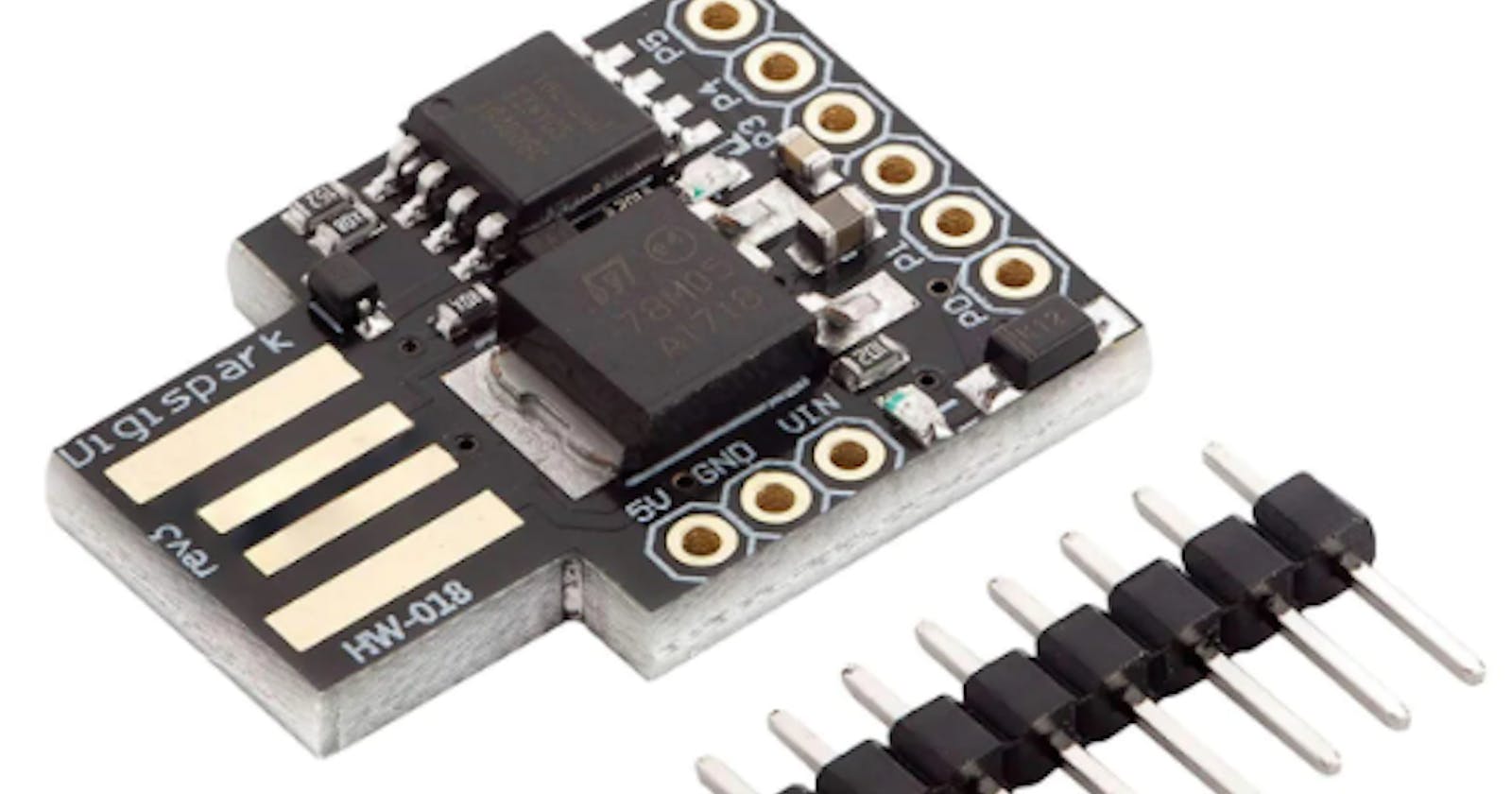
The board itself has a USB port for connecting to the computer and a few pins which can be used to read data from sensors or control items like LEDs. For this we will just focus on getting everything set up.
Software
You need software to get code onto your board. The software you use is Arduino IDE. At the time of writing (12th March 2024) the latest version is 2.3.2 and can be found here. If that link is dead try the main Arduino site and look for downloads or software.
Download and install that software.
Board Drivers
You now need to tell the Arduino all about your board and provide drivers for it. To do this open the Arduino software you've just installed. Click on File > Preferences. At the bottom you should see an option labelled, "Additional boards manager URLs". In the box paste this code:
https://raw.githubusercontent.com/digistump/arduino-boards-index/master/package_digistump_index.json
On the left hand side menu on the Arduino software you now need to select the Boards Manager.
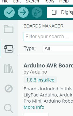
In the filter type in Digistump.
One of the options will be "Digistump AVR Boards". Click Install. This will install some software and ask for some permissions. At the end it may even say an installation has failed. That's nothing to worry about. Just carry on.
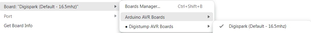
You now need to tell the Arduino software to use the correct Board. To do this click Tools > Board: > Digistump AVR Boards > Digispark (Default - 16.5mhz)
You're now set up.
Write Some Code
The Arduino IDE software uses "Sketches". These are simply programs which you upload to the board. A typical program would be to flash the LED on the Digispark ATTiny board.
In the Arduino software click "File" and select "New Sketch".
Copy and paste this code.
int Led_Int = 1;

void setup() {
pinMode(Led_Int, OUTPUT);
}

void loop() {
digitalWrite(Led_Int,HIGH);
delay(1000);
digitalWrite(Led_Int,LOW);
delay(1000);
}
Upload Code to the Board
This is where the first issue comes in. It feels like the right way to do this would be to plug the board into a USB port and then upload the code. However, this will not work. Instead you have to reverse that process. You upload the code, then insert the USB board.
Click the "Upload" button. This is the arrow which faces to the right, usually the second icon along from the left.

In the output at the bottom you will see something similar to:

Now you insert the board into a spare USB port. The code then gets uploaded to the board. Once it's done you can remove the board and it's ready to go.